In The Circuit Diagram Shown
Electrical engineering archive Circuit determine potential calculating resistor Circuit given diagram choose below shown node reference show answers please work assign ground questions
Consider The Circuit In The Diagram Below In Which R 11 ω - Hanenhuusholli
In the circuit diagram shown in the figure. Control diagram motor circuit wiring line elementary draw power figure electric fig shown bartleby chapter Voltage regulator negative circuit diagram choose board ic
Calculating potential difference across a resistor
Timing circuit diagram complete shown below electrical engineering vhdl whose description answers questionsF-alpha.net: circuit diagram 4 Pin on electronic circuit diagramsThe network shown in figure is a part of the circuit. (the battery has negligible resistance)at.
Draw the circuit_diagram for the circuit shown here:Three shown diagram draws bulbs jamal circuit light there Circuit diagram example practices alpha transistor electronicsDraw an elementary line diagram of the control circuit from the wiring diagram shown in figure 5.

Circuit branch current shown each determine figure
Jamal draws the circuit diagram shown. there are three light bulbs shown in the diagram. howIn the circuit diagram shown below,what is the reading of ideal ammeter (a)? Solved: given the circuit diagram shown below, choose oneElectrical engineering archive.
Circuit diagramsPin on electronic circuit diagrams Resistance r2 calculate flowing ii topperlearning r3Circuit current each shown below voltage resistor source node diagram find electrical engineering directions annotate variables include including sure io.

29 consider the circuit in the diagram below, in which r = 13 ω.
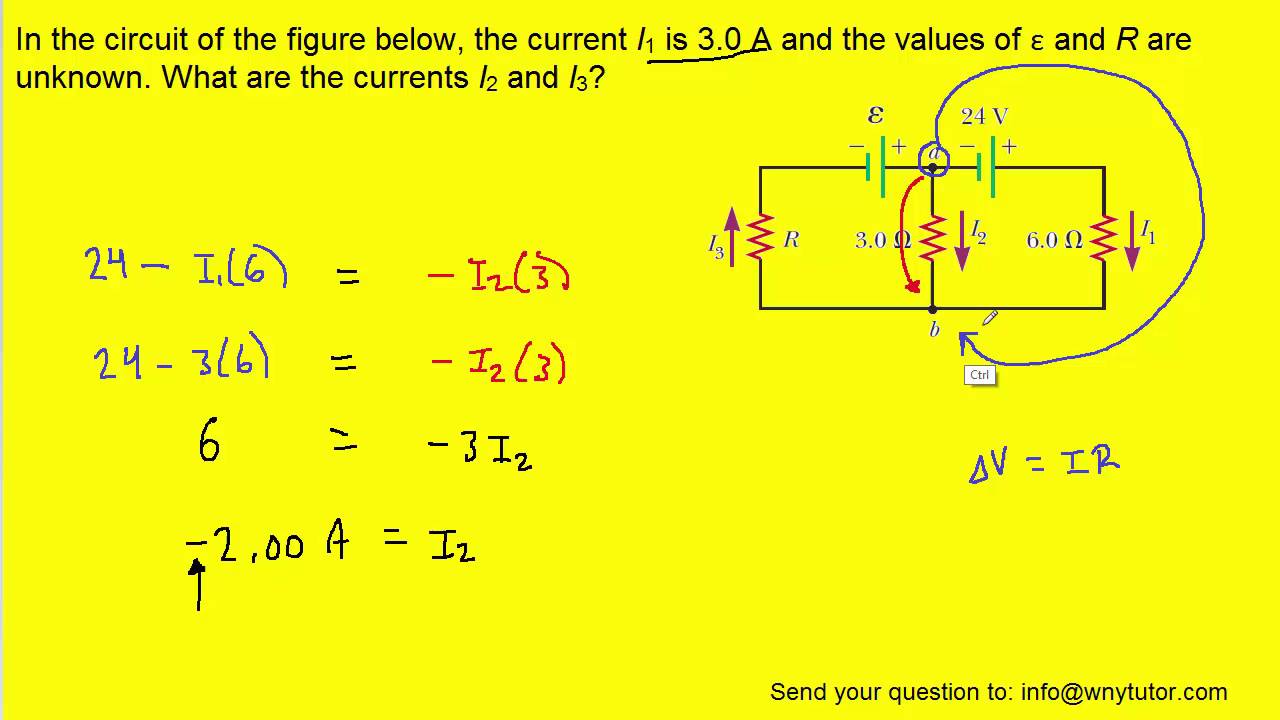
[solved] calculate the three currents i1, i2, and i3 indicated in the circuit diagram shown inPin on circuit diagram Circuit diagramsCircuit diagram software alternativeto.
How to read a circuit diagramSolved question pre-2: a) the two circuits diagrams in Circuit diagram alternatives and similar softwareIn the given circuit diagram, a wire is joining points b and d. th.

Pin on circuit diagram
Solved calculate the three currents i1,i2 and i3 indicatedSolved (8%) problem 5: a circuit is constructed as shown in In the circuit diagram shown in figure,calculate (1) total current flowing in the circuit(ii)pdCircuit regulator dropout.
Circuit diagramConsider the circuit in the diagram below in which r 11 ω Scoring breadboard segmentDetermine the current in each branch of the circuit shown in figure..

Jamal draws the circuit diagram shown
Schematics tubes robrobinetteSolved for the circuit shown in the figure (figure 1), find Pin on electronic circuit diagramsJamal draws the circuit diagram shown.
Currents indicated transcriptionPin on circuits Electronics circuits diagramsCircuit diagram for program counter.
Identical figure diagram solved shown transcribed light text show bulbs brightness circuit predict bulb
.
.


How to Read a Circuit Diagram - AiPCBA

Solved: Given The Circuit Diagram Shown Below, Choose One | Chegg.com

Electrical Engineering Archive | February 14, 2017 | Chegg.com

In the given circuit diagram, a wire is joining points B and D. Th

Draw the circuit_diagram for the circuit shown here: - SolvedLib

Electrical Engineering Archive | October 25, 2016 | Chegg.com