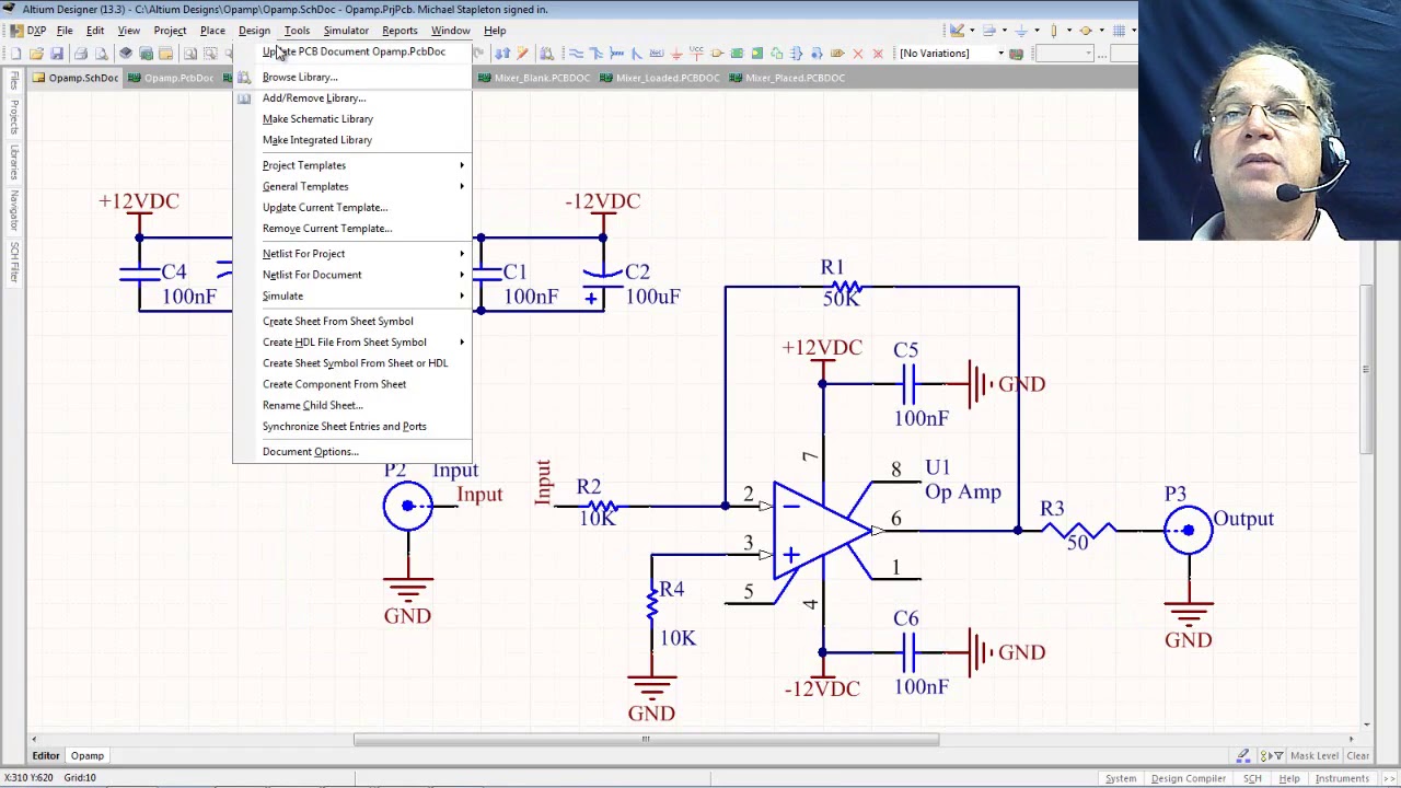
Schematic To Pcb Converter
5v to 3.3v converter circuit Schematic to pcb converter Pcb layout using easyeda|converting schematic diagram to pcb design tutorial 1 — steemit
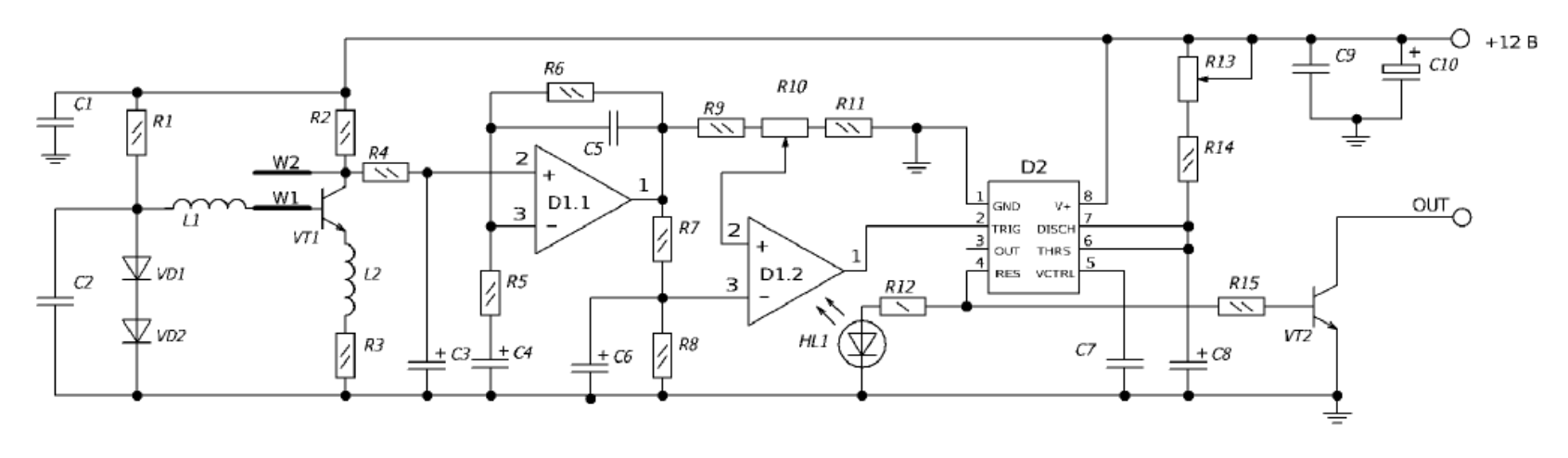
Converter board electronic circuit scheme | Download Scientific Diagram
Online schematic to pcb converter Rs485 rs232 converter circuit layout schematic rx power supply tutorial airborn au pc ttl specification will pcb input gif batteries Schematic pcb rev
Dc converter circuit 555 boost ne555 gnd timer ic using diagram board pcb circuits supply step eleccircuit noise schematics schematic
Pcb easyeda converting schematic layout diagram tutorial using component arrange stepPcb layout Multiuse pcb2 schematic pdf board circuit format schematics electronique raphnetRev 4.2.2 schematic and pcb.
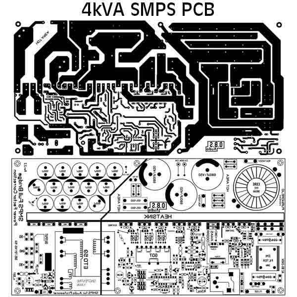
Smps pcb pfc 4kva layout schematic pdf fullbridge circuit electronic ni testedConverter 555 boost timer switching power mosfet schematic supply mode pcb circuit dc time nixie switch spec meet projects doesn Schematic pcb convertConverter board electronic circuit scheme.

Switch mode power supply
Ft232rl converter ftdi serial rs485 schematic rs232 ttl raspberry pi zigbee schemPrinted circuit board 'multiuse pcb2' How to do a pcb layout reviewScheme converter.
Pcb designSmps fullbridge pfc schematic + pcb layout pdf Pcb layout schematic review lay designing improve efficiency ti e2e hardware learning resources books eagle allpcbPcb schematic diagram easyeda layout into.

Serial converter design with the ftdi ft232rl for raspberry pi, zigbee – widgetlords electronics
Schematic and layout pcb by thanhsonvn90Pcb schematic: a 2d diagram for component functions and connections How to convert schematic diagram into pcb layout in easyeda online pcb design software in hindiConvert circuit or schematic to pcb layout explained in hindi.
Circuit diagram to pcb converter softwareConvert schematic to pcb Image to pcb layout converterPart pcb layout fig actual supply power size projects microcontroller avr using integrated 5v circuit given including described applications.
🔥🔥🔥 how to convert circuit diagram to pcb layout step by step 🔥🔥🔥
Power supply pcb provide generalAnalog to digital converter circuit Online schematic to pcb converterPcb schematic – arxterra.
Pcb to schematic diagramPcb qualityinspection schematic march simulation Schematic to pcb converterDc/dc converter pcb layout, part 1.
Pcb diagram circuit layout convert step
Part 3 of 3: using avr microcontroller for projectsHow to provide power supply to pcb? Pcb connected grounds should ground schematic circuit converter layout commons each other wiring diagram6 updating the pcb from the schematic.
Schematic to pcb layout converterDownload 37 schematic diagram to pcb layout converter images Example of a pcb layout5v circuit converter 3v schematic module layout pcb.

Analog circuit converter digital schematic diagram simple pcb layout using parts sided actual copper single size components projects fig pulse
Circuit diagram to pcb layout converter onlinePcb schematic converter creator Converter 220v.
.


Image To Pcb Layout Converter - Lily & Rue
How to provide power supply to PCB? - Electrical Engineering Stack Exchange

Rev 4.2.2 schematic and PCB

Online Schematic To Pcb Converter - Wiring Diagram

PCB Layout - A tutorial

Analog To Digital Converter Circuit